


Control valves play a pivotal role in modern industrial processes. They ensure the accurate regulation of fluid flow, pressure, and temperature. These devices are fundamental for the safe and efficient operation of systems in various industries.
In this article, we will explore what a control valve is, its key components, and its significance. We will also discuss the control valve symbol, the control valve diagram, and the control valve assembly.
What Is A Control Valve?
A control valve is a mechanical device used to regulate the flow and pressure of fluids in a pipeline or process system. Examples of these are liquids, gases, or slurries.
A control valve is the final control element in a process control loop — a power-operated device that varies the size of the flow passage in response to a signal from a controller, directly controlling flow rate and, consequently, process variables such as pressure, temperature, and liquid level.
IEC 60534 Standard: Control valve design, sizing, and performance are governed by the IEC 60534 series (formerly IEC 534). Specifically, IEC 60534-2-1 defines flow capacity calculation, IEC 60534-3 defines dimensions, and IEC 60534-8-3 defines noise prediction. Compliance with these standards ensures global interchangeability and is frequently required by EPC contractors in project specifications.
Unlike manual valves, which require physical actuation by an operator, control valves respond automatically to real-time process conditions. The control signal can be pneumatic (4–20 mA or 3–15 psi), electric, or hydraulic, depending on the system design and hazardous area classification.
Control valves are a critical component of process control systems. They receive signals from controllers to adjust their settings and maintain optimal operating parameters. These signals can be pneumatic, electrical, or hydraulic, depending on the system’s design.
The Role of a Control Valve in a Process Control Loop
In a closed-loop process control system, a control valve works alongside three other elements:
Sensor → Controller → Control Valve → Process → Feedback (repeats continuously)
- Sensor/Transmitter: Measures the process variable (flow rate, pressure, temperature) and sends the reading to the controller.
- Controller (PID): Compares the measured value against the desired setpoint and sends a corrective signal (4–20 mA or digital) to the valve.
- Control Valve (Final Control Element): Adjusts the flow passage area to bring the process variable back to the setpoint.
- Feedback Loop: The corrected process variable is re-measured, and the cycle continues.
This is why control valves are called the “final control element” — they are the last intervention point before a process variable drifts outside its acceptable operating range.
Control Valve Symbol
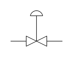
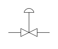
In process engineering, visual symbols are used to represent control valves on system diagrams. The control valve symbol usually consists of a valve body depicted by a square or a rectangle, with lines indicating the connection to pipelines.
These symbols are standardized to ensure universal understanding across industries. For instance, a globe valve might appear as a circle with two intersecting lines in the diagram. Other types of control valves, like ball or butterfly valves, have distinct variations of this symbol. This helps engineers and operators quickly identify their function and placement in the system.
P&ID Symbol Reference: On P&ID (Piping and Instrumentation Diagram) drawings, a control valve is represented by a balloon-shaped symbol with the tag number (e.g., FV-101). The actuator type is indicated above the valve body: a square with diagonal lines for pneumatic diaphragm, a triangle for electric, and a square with ‘T’ for hydraulic. A positioner is shown as a box with an arrow on top of the actuator symbol.
Pneumatic Diaphragm
Square with diagonal lines above the valve body.
Electric Actuator
Triangle symbol above the valve body.
Hydraulic Actuator
Square with ‘T’ above the valve body.
Positioner
Box with an arrow on top of the actuator symbol.
Control Valve Diagram
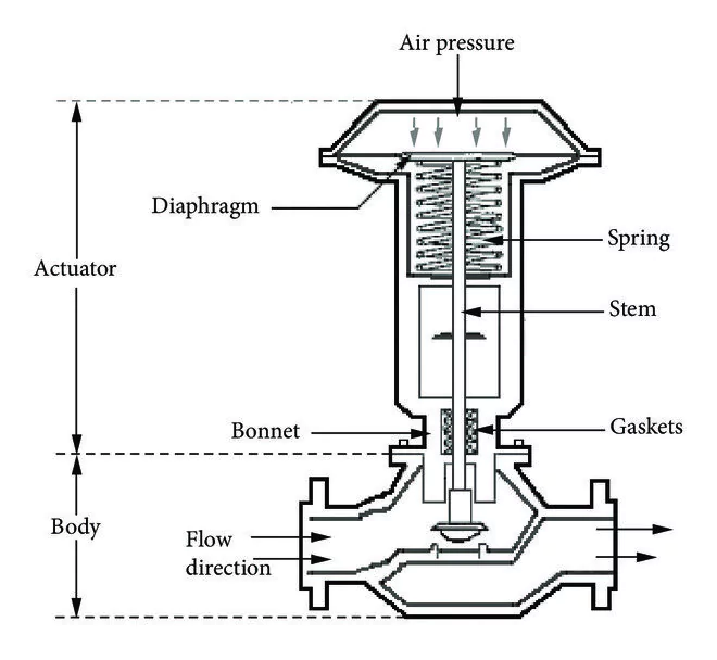
A control valve diagram provides a detailed illustration of the valve’s components and how they interact to regulate flow. It typically shows:
- Valve Body: The main housing that contains the internal components.
- Actuator: A device (pneumatic, electric, or hydraulic) that moves the valve mechanism.
- Positioner: Ensures the valve reaches the precise position needed to regulate flow as per the control signal.
- Flow Path: Demonstrates how the fluid enters and exits the valve.
This diagram is an essential tool for engineers to understand the operational flow, troubleshoot potential issues, and ensure proper maintenance.
Control Valve Assembly
The control valve assembly refers to the complete set of components that make up the control valve system. This assembly ensures the valve’s seamless operation in various industrial settings.
Simplified control valve assembly — annotated components
It includes:
- Valve Body: Houses the internal parts and determines the flow characteristics.
- Trim: Internal components like the plug, seat, and stem that directly affect flow control.
- Actuator: Provides the necessary force to move the valve’s trim.
- Positioner: Enhances the precision of the actuator, ensuring the valve opens or closes accurately.
- Accessories: Components such as solenoid valves, limit switches, and handwheels that support functionality and manual operation.
The design and assembly of these components determine the valve’s suitability for specific applications.
Flow Characteristics: Control valves exhibit different flow characteristics based on trim design:
- Linear: Flow is directly proportional to valve opening (ΔQ/Δstroke = constant)
- Equal Percentage: Each equal increment of stroke increases flow by a constant percentage
- Quick Opening: Large flow increase at small stroke, then levels off
The characteristic is selected based on process gain requirements: linear for pressure-controlled processes, equal percentage for most flow/temperature loops. For a detailed comparison of equal percentage vs linear control valve characteristics, see our dedicated guide.
Applications of Control Valves
Control valves are vital in numerous industries, including:
- Oil and Gas: Regulating crude oil flow, refining processes, and pipeline pressure.
- Chemical Processing: Ensuring precise mixing, pressure control, and reaction conditions.
- Power Plants: Managing steam flow to turbines and cooling systems.
- Water Treatment: Controlling flow rates in filtration, desalination, and distribution systems.
- Metallurgy: Regulating molten metal flow in production and cooling systems.
By enabling fine-tuned control of processes, control valves contribute to increased efficiency, safety, and cost-effectiveness.
How to Choose the Right Control Valve
Selecting the appropriate control valve involves several considerations:
- Process Requirements: Understand the fluid type, pressure, and temperature range.
- Valve Type: Choose from options like globe, ball, butterfly, or plug valves based on application needs.
- Material Compatibility: Ensure the valve materials are resistant to the fluid being handled, especially in corrosive environments.
- Control Precision: Evaluate the valve’s ability to respond accurately to control signals.
- Manufacturer Expertise: Opt for trusted, experienced manufacturers known for delivering quality products and services.
What to Specify When Sourcing a Control Valve — RFQ Checklist
When sending an RFQ to a manufacturer, provide:
Fail-Safe Action Explained: The ‘fail-safe action’ in the RFQ checklist determines valve behavior upon loss of control signal or air supply:
- Fail-Open (FO): Valve opens fully on signal loss — used for cooling water, emergency vents
- Fail-Close (FC): Valve closes on signal loss — used for fuel gas, toxic media, safety isolation
- Fail-Last (FL): Valve holds last position — used where process interruption is worse than wrong position
Selection is driven by HAZOP analysis and SIL (Safety Integrity Level) requirements defined in IEC 61508.


 CHINA
CHINA LIBERIA
 FRANCE
 BARBADOS
 KIRIBATI

